
3D Printing in Manufacturing
3D printing is not a new technology. It started in the 80’s and at the time was mainly used for rapid prototyping. Since then, it has continued to play an important role in manufacturing and expanded from prototypes to include custom jigs, tools, and parts.
What is 3D Printing?
3D printing, also known as additive manufacturing, is the process of making three-dimensional solid objects, one layer at a time from a digital file. 3D printing manufacturing is the opposite of traditional subtractive manufacturing, and it allows the production of complex shapes using less material than traditional manufacturing methods. Check out this video of the 3D manufacturing process.
Benefits of 3D Printing
– Rapid prototyping and rapid manufacturing: 3D printing can take hours or days rather than weeks, and there is no need for expensive tools or machining.
– Design freedom: Geometries that were once difficult can now be achieved. These designs have become simpler to construct through 3D printing. Shapes, holes, and interior cavities are much easier using a 3D printer.
– Less waste: 3D printers use resources more efficiently than traditional forms of subtractive manufacturing.
– Less weight: Parts can weigh less while still being strong. Carbon fiber, Kevlar, and other strong materials can be added to the material for an even stronger part.
– Improved surface textures: 3D printers can create surface textures that are impossible to duplicate with traditional manufacturing.
– More affordable: It is more affordable to create parts through additive manufacturing at rates much cheaper than traditional machining. There is no need to pay a machinists or tie up a CNC machine, and there is no left over material to deal with.
– Localized manufacturing: Businesses are able to keep manufacturing in-house rather than outsourcing it.
Challenges of 3D Printing
– Cost of the equipment: 3D printers can be very expensive upfront.
– Post-processing needs: Supports need to be removed after the part comes out of the 3D printer and sanding may be required.
– Lower strength: Although parts can be reinforced with strong carbon fiber or Kevlar fibers, it will never be as strong as a standard steel part.
– Slow: 3D printers are slow and are not the best option if you need to make a large amount of a single part in a short amount of time.
Flex Machine Tools Embraces Additive Manufacturing
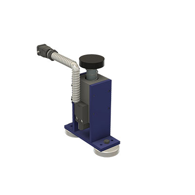
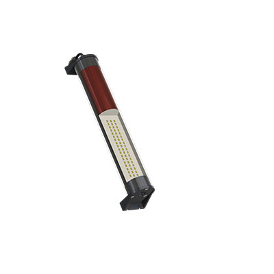
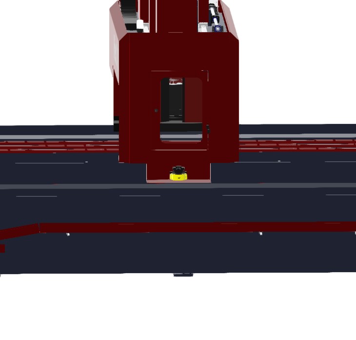
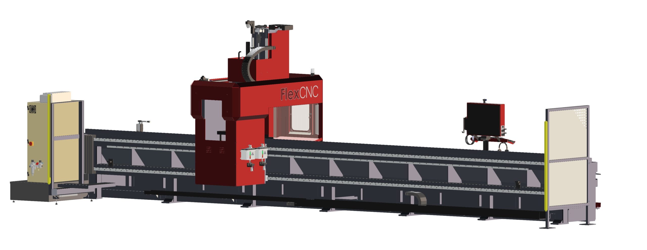
Flex Machine Tools originally bought a 3D printer to make prototypes for tool holders. They quickly realized the strong nature of the material would allow them to fully manufacture these parts in the 3D printer. Their 3D printing efforts now include custom end-effectors and spare/replacement parts for the FlexCNC.
With 3D printing, the options are (almost) endless when it comes to what materials can be used. Flex Machine Tools uses a custom material called onyx for all 3D printed parts. The onyx is integrated with chopped carbon, which is three-and-a-half times stiffer than nylon while still being light in weight. The onyx can be reinforced with carbon fiber, Kevlar, and fiberglass for an even stronger material.
The main reason Flex Machine Tools uses 3D printing technology is the cost-saving measures it provides. Machinists no longer have to be tied up making a custom part that can easily be made using a 3D printer. The 3D printer is automated so you can set it and forget it until the part is finished. This frees up the CNC machine for parts where the material properties are essential.
Despite the challenges, 3D printing is continually evolving and becoming a larger part of the manufacturing industry. This technology enhances innovation and adds value to operations, so it is important to ensure that the technology fits the product and makes sense for the business. Flex Machine Tools found a way to include 3D printing into their daily operations, and they will continue to use the technology as it further evolves.
For more articles on popular topics in the machining industry, check out the Flex Machine Tools blog.